.
Physics SS 3
Theme 1 Conservation Principles
Theme 2 Waves, Motion without Material Transfer
Theme 3 Fields at Rest and In Motion
Theme 4 Energy Quantization and Duality of Matter
Theme 5 Physics in Technology
Table of Contents
Energy sources are the various forms of natural resources that can be converted into usable energy for various purposes. These sources can be categorized into two main types: primary and secondary. Primary sources include fossil fuels (coal, oil, natural gas), renewable sources (solar, wind, hydro, geothermal), and nuclear fuels. Secondary sources are derived from primary sources and include electricity and hydrogen.
Renewable sources of energy are those that can be naturally replenished over a relatively short period of time. Examples include solar energy (from sunlight), wind energy, hydroelectric energy (from flowing water), and geothermal energy (from Earth’s heat). Non-renewable sources, on the other hand, are finite and deplete over time as they are used. These include fossil fuels (coal, oil, natural gas) and nuclear fuels. The key distinction is that renewable sources are sustainable in the long term, while non-renewable sources are not.
Energy is essential for the development of society as it powers various aspects of modern life. It is used for electricity generation, transportation, heating, cooling, industrial processes, and more. Reliable and affordable energy access is a cornerstone of economic growth, technological advancement, and improved living standards. Without energy, many of the conveniences and technologies we rely on today would not be possible.
Energy usage, particularly from non-renewable sources, has significant environmental impacts. Burning fossil fuels releases greenhouse gases (such as carbon dioxide) into the atmosphere, contributing to climate change and global warming. Extracting and processing these fuels can lead to habitat destruction, air and water pollution, and oil spills. Nuclear energy, while low in carbon emissions, poses risks in terms of radioactive waste disposal and potential accidents. These environmental impacts highlight the importance of transitioning to cleaner and more sustainable energy sources.
Renewable energy sources like solar, wind, hydro, and geothermal are generally considered environmentally friendly because they produce little to no greenhouse gas emissions during operation. They have minimal negative impacts on air and water quality. Fossil fuels and nuclear energy, on the other hand, are more hazardous to the environment due to their emissions, waste products, and potential for accidents.
Conservation of energy refers to the practice of using energy resources more efficiently and responsibly to reduce waste and environmental impact. This involves adopting energy-saving technologies, improving energy efficiency in buildings and transportation, and promoting sustainable practices. Conservation helps extend the availability of finite resources, reduces pollution, and mitigates the impacts of energy consumption on the environment. It’s a crucial component of a sustainable energy future.
Remember that these explanations provide a broad overview of each topic. There are many complexities and nuances within each area, but I hope this helps you understand the basics of energy sources, their impact on society and the environment, and the importance of conservation.
Energy conversion, also referred to as energy transformation, entails the process of altering energy from one form to another.
Transformation of mechanical energy results in heat energy.
Conversion of electrical energy leads to mechanical energy, as seen in devices like blenders and electric cookers.
Electricity can be converted into heat energy, as demonstrated by appliances like clothes irons and electric stoves.
Mechanical energy can be transmuted into electrical energy. Chemical energy can be changed into heat energy, exemplified by the usage of kerosene stoves. Solar energy can be metamorphosed into heat energy, chemical energy, and electrical energy. Light energy can be modified into heat energy.
A wave is a phenomenon characterized by the transfer of energy through a medium without the physical movement of the medium itself over a long distance. Waves can take various forms, including mechanical waves, which require a medium (like air, water, or solid material) to travel through, and electromagnetic waves, which can propagate through a vacuum (such as light or radio waves).
Electromagnetic waves, on the other hand, consist of oscillating electric and magnetic fields that can travel through a vacuum. These waves include various forms of light, such as radio waves, microwaves, infrared radiation, visible light, ultraviolet radiation, X-rays, and gamma rays.
Waves play a crucial role in various natural phenomena and technological applications. They are essential for communication (radio, TV, and cellular signals), medical imaging (X-rays and ultrasound), and understanding the behaviour of particles at the atomic and subatomic scales.
The attributes of waves manifest in diverse ways, conveniently demonstrated through the use of a ripple tank. The apparatus comprises a transparent container filled with water, beneath which lies a white screen. Positioned above is a light source, while a small electric motor (vibrator) is attached to induce disturbances that give rise to waves. The movement of wavefronts delineates the patterns of these waves during their propagation.
One of the inherent traits of waves involves their travel in unswerving trajectories, perpendicular to their wavefronts. The ensuing illustrations portray the direct course of water waves as they advance.
Refraction is the phenomenon where waves alter their trajectory upon crossing a boundary between different mediums. This transformation arises when waves encounter an obstacle obstructing their path. Notably, this directional shift materializes specifically at the juncture between deep and shallow waters, and solely when waves strike the boundary at an angle.
When waves traverse the edge of an obstacle or a narrow aperture, they incline to curve around the corner and disperse beyond the hindrance or opening.
Wave interference unfolds when two waves conflate, yielding outcomes that can range from significantly amplified waves to diminished ones, or even the absence of waves entirely. In-phase waves combine constructively, intensifying their effects. Conversely, out-of-phase waves nullify each other, leading to destructive interference.
In an illustration of sound interference, two loudspeakers, L1 and L2, are linked to a common signal generator, aligning the phases of their emitted sound waves. Positioned roughly half a wavelength apart (around 0.5 meters for a sound frequency of 1,000 Hz), the speakers exhibit alternating increments and decrements in sound intensity along line AB. This occurrence demonstrates both constructive and destructive interference.
Stationary waves, also recognized as standing waves, manifest when two identical progressive waves moving in opposing directions superimpose. Placing two opposing speakers face to face or securing one end of a rope produces these stationary wave patterns.
Electromagnetic Waves: These are waves that consist of oscillating electric and magnetic fields. They do not require a medium (substance) to travel through and can propagate through vacuum (empty space). Examples include radio waves, microwaves, infrared radiation, visible light, ultraviolet radiation, X-rays, and gamma rays.
Mechanical Waves: These waves require a medium to travel through, such as a solid, liquid, or gas. They involve the physical displacement of particles in the medium as the wave passes through. Examples include sound waves, water waves, and seismic waves. The key distinction is that electromagnetic waves can travel through vacuum, while mechanical waves require a physical medium for propagation.
Electromagnetic waves and mechanical waves have distinct characteristics, uses, and sources. Frequency and wavelength are essential properties of waves that are interconnected and play roles in determining wave behavior and applications.
Electromagnetic waves are produced by electromagnetic vibrations. Electromagnetic waves have an electrical origin and the ability to travel in a vacuum. So, electromagnetic waves are regarded as a combination of travelling electric and magnetic forces which vary in value and are directed at right angles to each other and to the direction of travel. In other words, they are transverse waves.
The electromagnetic waves consist of the following:
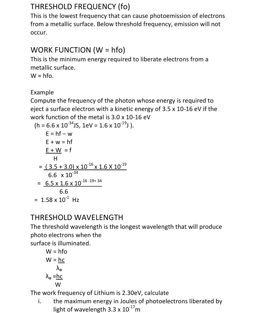
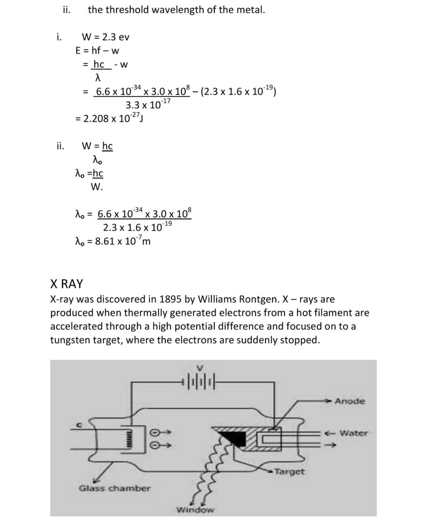
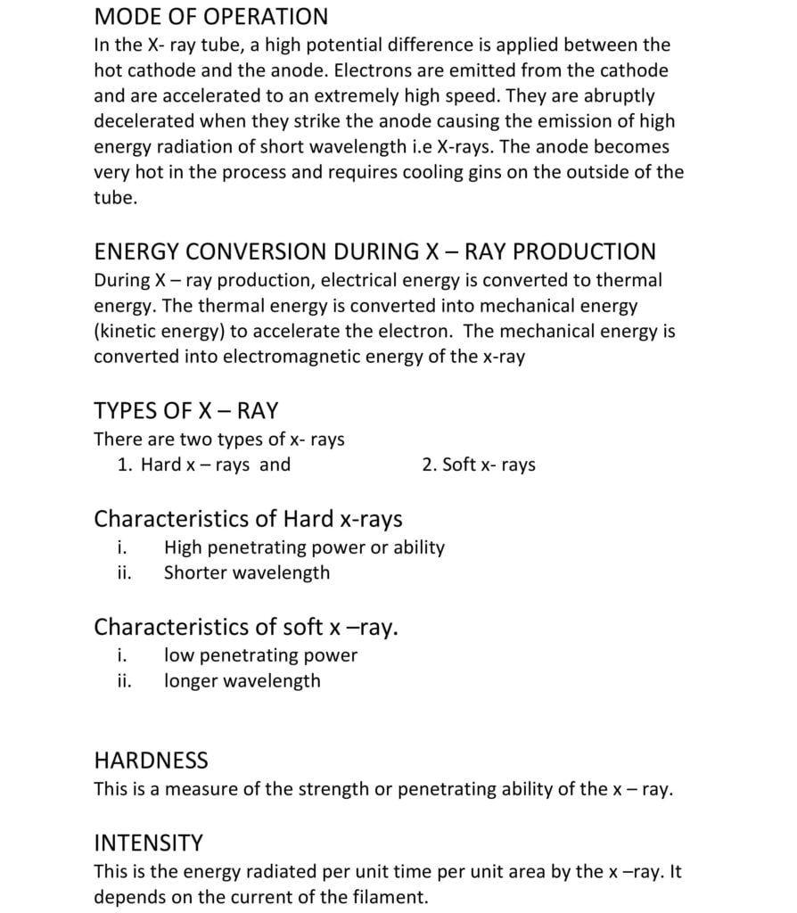
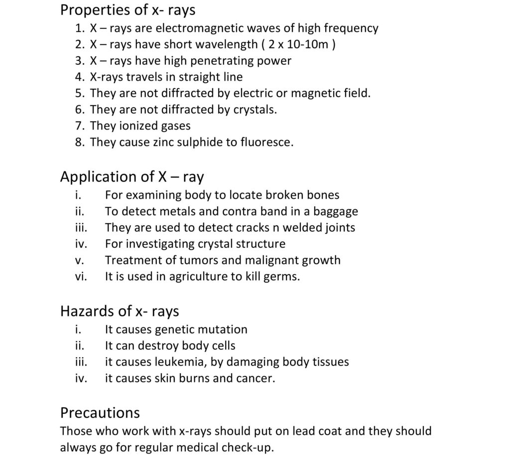
X-rays ionize gases and have a penetrating effect such that they pass through substances opaque to white light are diffracted by crystals and are unaffected by either electric or magnetic fields.
The detectors of the various radiations in the electromagnetic spectrum are
F = G x M1 M2/r2
where F is the gravitational force between two masses m1 and m2, r is the distance between their centres, and G is the gravitational constant.
Vesc = ∫2.G.M/r
where M is the mass of the celestial body (e.g., Earth), r is the distance from the object to the centre of the celestial body, and G is the gravitational constant. The escape velocity is derived using the principles of potential and kinetic energy and is based on the inverse square law, which relates the intensity of a force to the square of the distance from the source of that force.
A galvanometer is an instrument used to detect small electric currents. To convert a galvanometer into an ammeter (a device that measures current) or a voltmeter (a device that measures voltage), a shunt resistor or a series resistor is added, respectively.
The potentiometer is a device used to measure the electromotive force (emf) or potential difference between two points in an electrical circuit. It operates on the principle of the potential gradient along a uniform wire. When a constant current flows through the wire, the potential difference across any segment of the wire is directly proportional to its length. By adjusting a sliding contact along the wire, the point where the potential matches the unknown potential can be determined. This provides a means to measure unknown voltages by comparing them to a known voltage.
– To solve problems related to electric field intensity and electric potential, you typically apply the principles of Coulomb’s law and the formulas derived from it. Coulomb’s law gives the electric field due to a point charge, while the electric potential due to a point charge is calculated using the formula V = kQ/r, where k is the electrostatic constant, Q is the charge, and r is the distance.
1. Coulomb’s Law: Coulomb’s law states that the magnitude of the electrostatic force between two point charges is directly proportional to the product of their magnitudes and inversely proportional to the square of the distance between them. Mathematically, F = k * |q1 * q2| / r^2, where F is the force, q1 and q2 are the charges, r is the distance between them, and k is the electrostatic constant.
2. Solving Questions: To solve problems related to Coulomb’s law, you apply the formula mentioned above. You can calculate the force between charges, the magnitude of charges given a force, or distances given force and charges.
Remember to use consistent units and pay attention to the signs of charges to ensure accurate calculations.
However, most common types of capacitors are in the form of two parallel plate conductors which are separated by a very small distance, d. The two plates of the capacitor can be made to carry equal and opposite charges by connecting the capacitor across the terminals of a battery such that the potential difference across the plate is V.
Capacitor is represented as
The capacitance of a capacitor is defined as the ratio of the charge Q on either conductor to the potential difference V between the two conductors
C = Q over V
Q = CV
The SI unit of capacitance is the farad (F) which is equivalent to coulomb per volts (CV-1)
Factors that affect the capacitance of a capacitor are:
For a parallel plate capacitor, the capacitance C is given by
C = A over d
Where:
A= area of the plates
d= their separation
ɛ= permittivity of the dielectric medium (Fm-1)
If two or more capacitors is c1, c2 … are connected in series, it can be shown that the equivalent or net capacitance, c of the combination is given by:
1/c = 1 over c1 + 1over c2 +…
If they are connected in parallel the net capacitance C in this is given by:
C = c1 + c2 + …
Note that the opposite is the case if these were resistance.
A capacitor contains a charge of 4 .0 x 10 raise to power minus 4 coulomb when a potential difference of 400 v is applied across it. Calculate the capacitance of the capacitor
The capacitance C = q divided by v
= 4.0 times 10 raise to the power of minus 4, then divided by 400
= 10 raise to the power of minus 6 F
= 1.0f
A charge is a store of electrical energy. When a charge, q , is moved through a p.d , the work done is given by
W = average p.d times charge
= half of qv = half of QV
But v = Q over C; V = Q, divided by C
W = half of Q / C times q =half of q square/c
W = half of Q/C
Using Q = CV
W =1/2CV raise to the power of 2
Therefore, the work done is either
¼1 over 4 times q square divided by C or half of cv raise to power 2, which is W = half of CV raise to power 2.
This work is stored in the capacitor as electrical potential energy
A magnet is any material that is capable of attracting other pieces of the same material as well as pieces of iron. A substance is said to be ferromagnetic if it is attracted by a magnet. Examples are iron, cobalt, Nickel, and certain alloys. Substances which cannot be attracted by a magnet are called non-magnetic material e.g. brass, wood, copper, and glass.
Magnetization is a process whereby a material is made to become magnetic. This can be achieved through any of the following methods:
This is a process whereby a magnet is made to lose its magnetism. Demagnetization can be achieved by:
Electrical Method – The magnet is placed in a solenoid through which an alternating current is flowing. The solenoid is placed with its axis pointing in the East-West direction. After a few seconds, the magnet is slowly withdrawn out of the solenoid to a long distance away. This is the most efficient way of demagnetizing a magnet.
Mechanical Method – Another method of demagnetizing magnets is to hammer it hard when it is pointing in the East-West direction.
Heating Method – When magnets are strongly heated, it lose their magnetism.
Soft iron is pure iron while steel is an alloy of iron and carbon. Steel is a much harder and stronger material than soft iron. Steel and iron have different magnetic properties.
Iron is easily magnetized than steel but it readily loses its magnetism. Steel produces a stronger magnet which is the reason why steel is used for making permanent magnet such as compass needle. In temporary magnets where the magnetism is required for a short
Magnetic field is the space surrounding the magnets in which magnetic force is exerted. It is a vector quantity and it is represented by magnetic lines. The direction of the magnetic flux at any point is the direction of the force on a north pole placed at that point.
In the neighbourhood of two magnets placed closed together, there exists a field in which the direction of the magnetic flux changes rapidly in a confined space. The magnetic flux can be obtained by using iron fillings.
A magnetic meridian at any place is a vertical plane containing the magnetic axis of a freely suspended magnet at rest under the action of the earth field.
The geographical meridian at a place is a plane containing the place and the earth’s axis of rotation.
The angle between the magnetic and geographical meridian is called the magnetic declination.
The angle of dip or inclination is the angle between the direction of the earth magnetic flux and the horizontal.
When a charged particle, such as an electron or a proton, moves through a magnetic field, it experiences a force known as the magnetic force. This force is perpendicular to both the velocity of the charged particle and the direction of the magnetic field. The relationship between the magnetic force and the motion of the charge can be described by the Lorentz force equation:
F = Q x V x B
Where:
F is the magnetic force experienced by the charge.
Q is the charge of the particle.
V is the velocity of the particle.
B is the magnetic field vector.
This equation tells us that the magnetic force is directly proportional to the charge of the particle, the magnitude of its velocity, the strength of the magnetic field, and the sine of the angle between the velocity and the magnetic field direction. The magnetic force doesn’t do any work on the charged particle; it only affects its direction, causing it to move in a circular or helical path, depending on the initial velocity and the orientation of the magnetic field.
(a) Angle of Declination:
The angle of declination, also known as the magnetic declination or magnetic variation, is the angle between the direction of the true geographic north (geographic meridian) and the direction of the north pole of a magnetic compass needle. In other words, it represents the difference between true north (geographic north) and magnetic north. This angle varies based on your location on Earth and changes over time due to the movement of Earth’s magnetic poles.
(b) Angle of Dip:
The angle of dip, also known as the magnetic inclination, is the angle between the direction of a magnetic needle that moves freely in the vertical plane and the horizontal plane of the Earth. It indicates how much the magnetic field lines are inclined from the horizontal at a specific location. At the magnetic equator, the angle of dip is 0 degrees (parallel to the Earth’s surface), while at the magnetic poles, it’s 90 degrees (pointing directly downward).
(c) Neutral Point:
In the context of Earth’s magnetic field, a neutral point is a location where the horizontal component of the Earth’s magnetic field is so strong that it neutralizes the vertical component. At this point, a magnetic needle will not show any inclination (angle of dip), as it will align parallel to the Earth’s surface. Neutral points are important when considering the behaviour of magnetic compass needles and their inclination in various locations.
These terms are essential in understanding the behavior of magnetic fields, compasses, and how Earth’s magnetic properties vary across different locations.
Magnetic field patterns can easily be observed using iron fillings. The magnetic is put on paper and the iron fillings are sprinkled lightly on the paper around the magnet. The paper is tapped gently and the iron fillings are found to turn and set to in a definite direction.
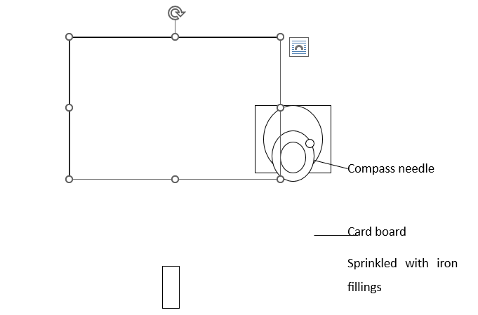
A straight conductor carrying current can be shown that it has a magnet filed around it. Allow a thick isolated copper wire to pass vertically through a hole in a cardboard shit. As shown below, sprinkle some iron fillings uniformly on the cardboard around the vertical wire connect the ends of the wire to a battery, switch on the current and place some compass needles around the wire. Note the direction to which the compass needle point. Switch on the current and note the swing of the needles and how they point.
It will be observed that when current is switch on and the card board is gently tapped, the fillings arrange themselves in a series of concentric circles about the wire as centre. Also as soon as the current is switch on, the needles will swing around and form a circle with the wire as centre. The direction of the filed depends on the direction of flow of the current. Such a direction can always be obtained by applying the Right Hand Grip Rule.

A conductor carrying an electric current, when placed in the magnetic field experiences a mechanical force. This can be demonstrated by using two metal rails fixed on each side of a powerful horse-shoe magnet. A copper rod is placed across the rays. When the current is passed through this copper rod, it is observed that the copper rod rolls along the rays, toward the right. If by adjusting the rheostat, more current is made to flow through the rod. One will notice that the rod moves faster, thus the force on the rod increases when the current increases.
If the direction of flow of current is reversed by reversing the connections at the battery terminals, the rod will be observed to move towards the left, opposite to the previous direction of motion.
If one turns the magnet such that the magnetic field is parallel to the length of the rod as shown below, it will be observed that the current carrying the rod remains stationary no matter the amount of current hat pass through. There is therefore no force on the rod.
This is a field representing the joint interaction of electric and magnetic forces. It is exerted on charged particles. The force on a charge q moving with velocity v less than the velocity of light is given by
F = q (E + v x B)
A conductor carrying an electric current when placed in a magnetic field experiences a mechanical force. It can be demonstrated by using two metal rails fixed on each side of a powerful horseshoe magnet. A copper rod is placed across the rails. When we pass current through this copper rod, it is observed that the copper rod rolls along the rails, towards the right. If by adjusting the rheostat, we cause more current to flow through the rod, we will observe that the rod moves faster. Thus, the force on the rod increases when the current increases.
The direction of force on a current carrying conductor placed perpendicular to the magnetic field is given by Fleming’s left-hand rule which is stated as follows:
If the thumb, forefinger and middle finger are held mutually at right angles to one another with the fore-finger pointing in the direction of magnetic field, and the second finger in the direction of Current, then the thumb will point in the direction of the force producing motion.
(a) A rectangular coil of insulated wire, known as armature
(b) A powerful magnetic field in which the armature turns is provided by two curve pole pieces of a powerful magnet
(c) A commutator consisting of a split copper ring, two halves of which are insulated from each other.
(d). Two carbon brushes which are made to press lightly against either side of the split-ring commutator
Electromagnetic Induction: This is the process of generating an electromotive force (EMF) or voltage in a circuit by changing the magnetic field through the circuit. This phenomenon was discovered by Michael Faraday in the early 19th century. Electromagnetic induction is based on the principle that a change in magnetic field flux through a closed circuit induces a voltage and, consequently, an electric current in that circuit.
Fleming’s Rules: these are a set of three rules that describe the direction of induced current and the motion of a conductor in relation to the magnetic field. These rules were formulated by John Ambrose Fleming and help determine the direction of the induced current or the motion of the conductor in electromagnetic induction situations.
Faraday’s First Law: This law states that when there is a change in magnetic flux through a closed circuit, an electromotive force (EMF) is induced in the circuit. The magnitude of the induced EMF is directly proportional to the rate of change of magnetic flux.
Faraday’s Second Law: This law states that the induced EMF in a closed circuit is equal to the negative rate of change of magnetic flux. Mathematically, this can be represented as: EMF = -d(Φ) / dt, where EMF is the induced electromotive force, Φ is the magnetic flux, and dt is the change in time.
Both of Faraday’s laws are based on the conversion of mechanical energy (motion or change in magnetic field) into electrical energy (induced EMF and current). The change in the magnetic field or motion of a conductor induces an electric current by exploiting the relationship between magnetic fields and electric fields.
Induction Coils: Induction coils are devices that use electromagnetic induction to amplify low-voltage signals to higher voltages. They consist of two coils, a primary and a secondary, wound around a common iron core. When the current in the primary coil changes, it induces a changing magnetic field, which in turn induces a voltage in the secondary coil.
Transformers: Transformers are devices that utilize electromagnetic induction to change the voltage level of alternating current (AC) while maintaining power efficiency. They consist of primary and secondary coils wound around a shared iron core. Transformers can step up (increase voltage) or step down (decrease voltage) AC voltages.
Lamination of Transformer and Induction Cores:
The cores of transformers and induction coils are laminated to reduce energy losses due to eddy currents. Eddy currents are small circular currents that can form within the core material when it’s exposed to a changing magnetic field. These currents generate heat and waste energy. Laminating the core with thin sheets of a material like silicon steel reduces the formation of eddy currents and thus improves the efficiency of the device.
AC Generators (Alternators): AC generators, also known as alternators, are devices that convert mechanical energy into alternating current (AC) electrical energy. They work on the principle of electromagnetic induction. The generator consists of a rotating coil within a magnetic field. As the coil spins, the magnetic field through the coil changes, inducing an alternating voltage.
DC Generators: DC generators, also known as dynamos, convert mechanical energy into direct current (DC) electrical energy. They also operate based on electromagnetic induction. The key difference is in the commutator and brush arrangement. A commutator in a DC generator reverses the direction of the current every half rotation, resulting in a unidirectional current flow.
Electromagnetic induction is the process of generating an EMF in a circuit due to changes in magnetic field flux. Fleming’s rules help determine the direction of induced current. Faraday’s laws describe the quantitative relationship between induced EMF and magnetic flux changes. These principles are applied in various devices like induction coils and transformers, with laminated cores to minimize energy losses. AC and DC generators both utilize electromagnetic induction, but they differ in their current output and mechanism of generating a unidirectional current.
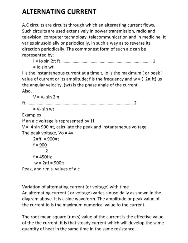

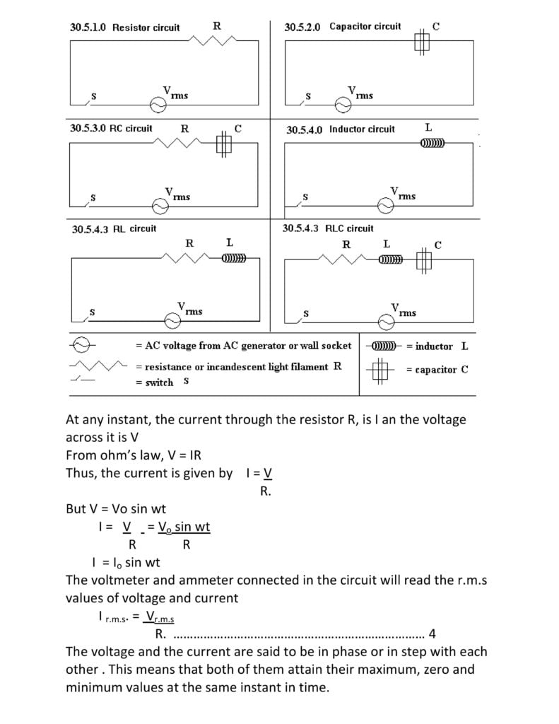
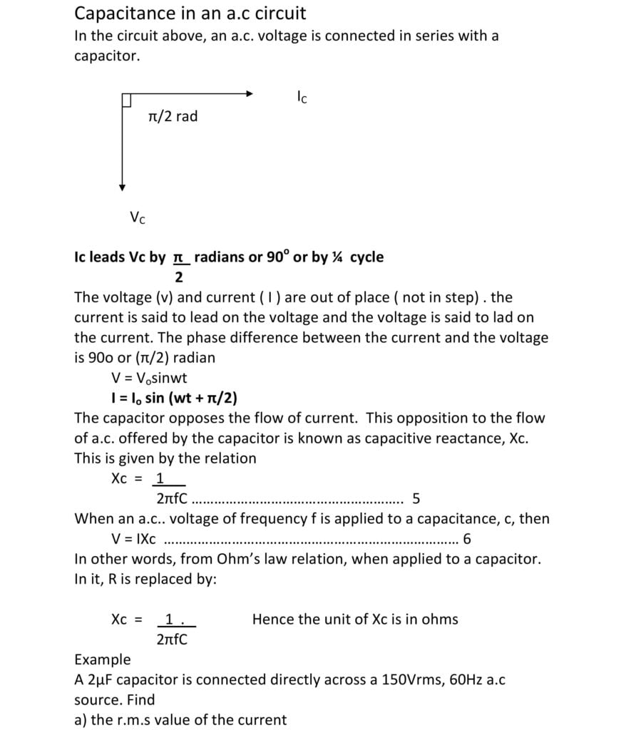
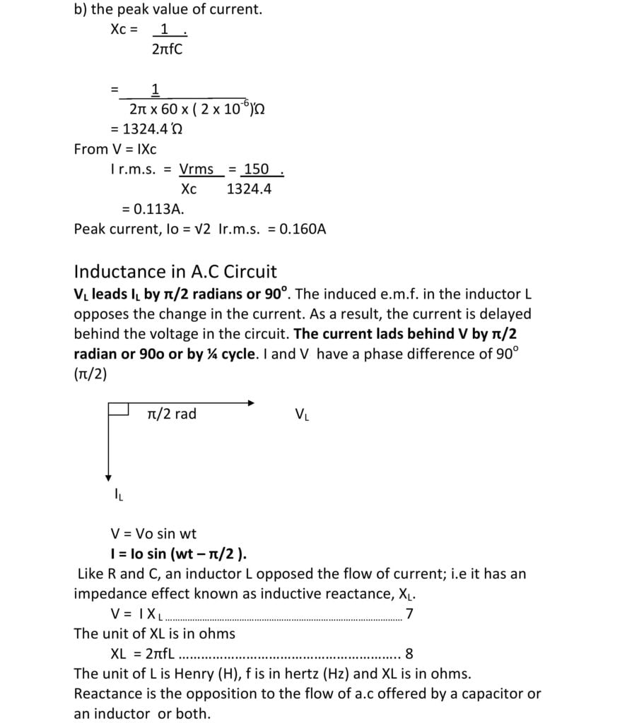
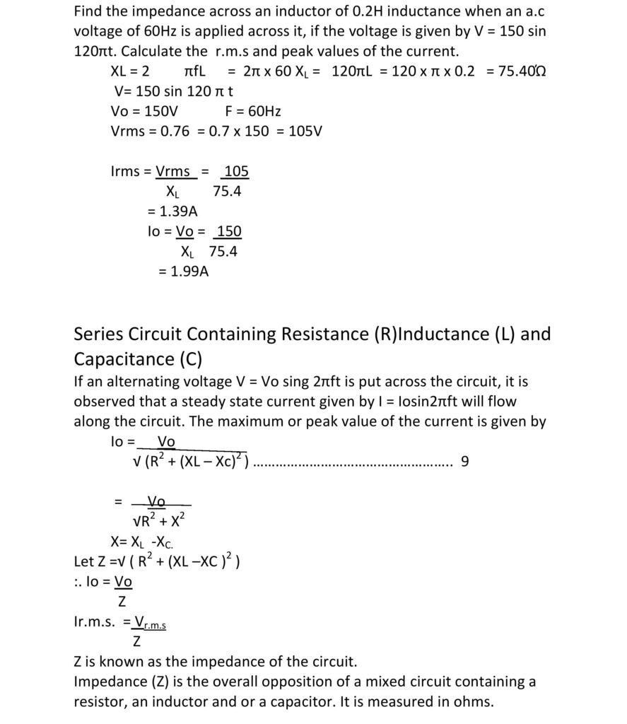
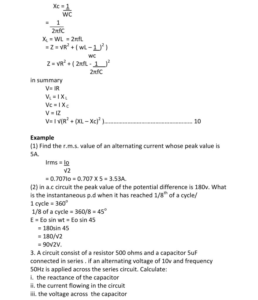
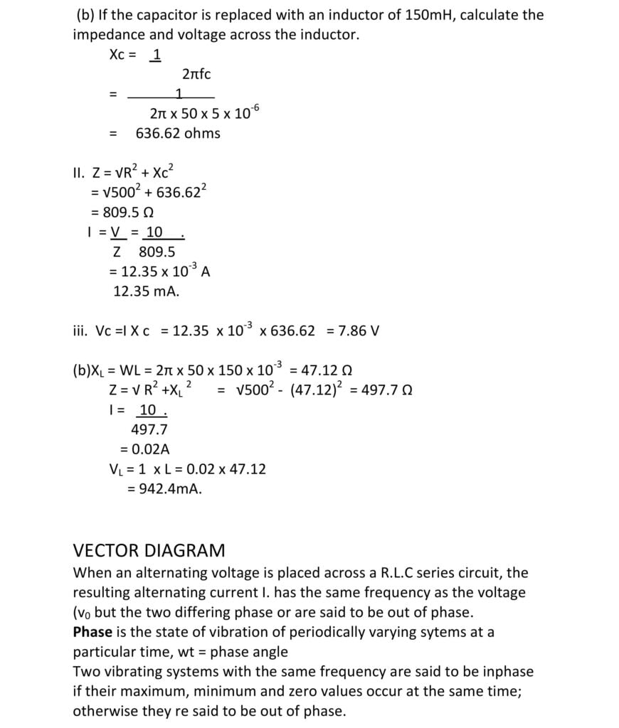
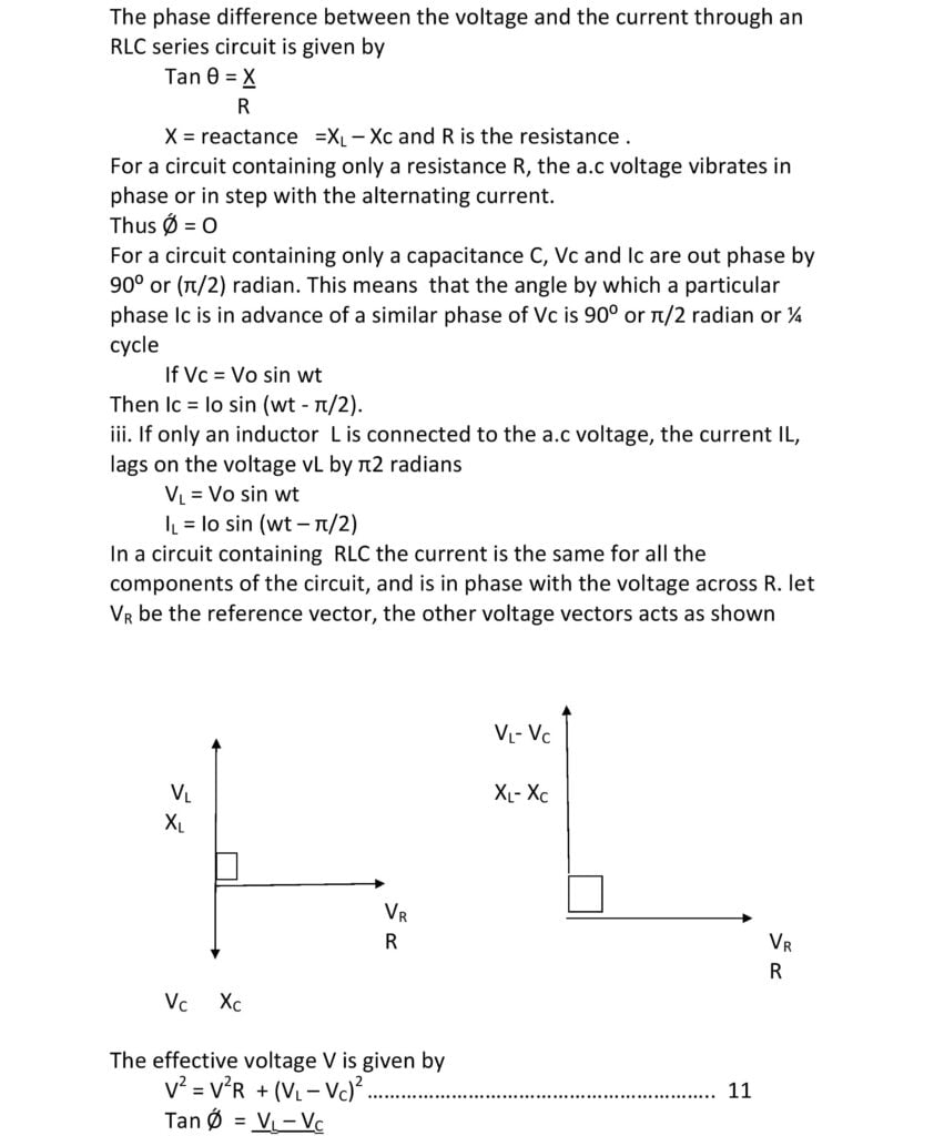
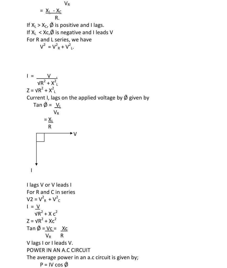
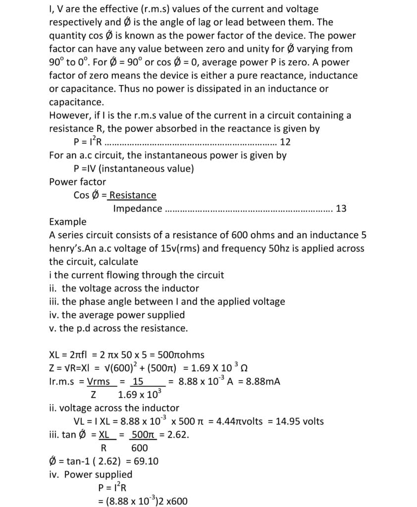
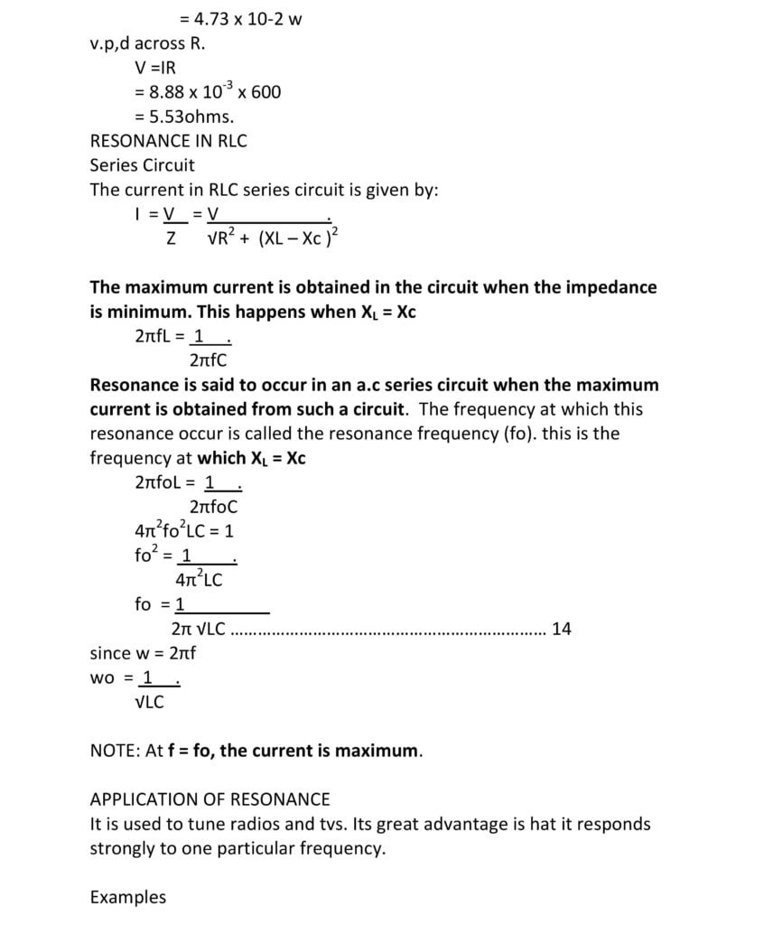
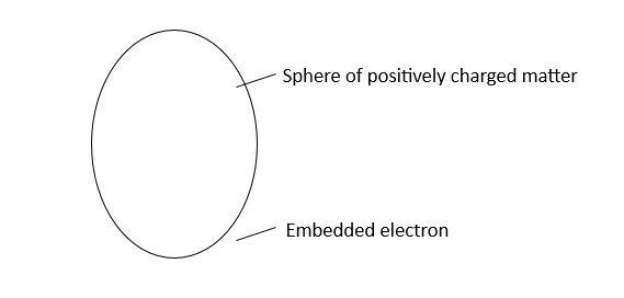
Thompson proposed an atomic model which visualized the atom as a homogenous sphere of positive charge inside of which are embedded negatively charged electrons.
He also determined the ratio of the charged to mass, e/m, of electrons, and found e/m to be identical for all cathode rays particles, irrespective of the kind of gas in the tube or the metal the electrons are made of.
He proposed a planetary model of the atom which suggested that the atom consists of a positively charged heavy core called the nucleus where most of the mass of the atom is concentrated around this nucleus, negatively charged electrons circle in orbits much as planets move around the sun. Each nucleus must be surrounded by a number of electrons necessary to produce an electrically neutral atom
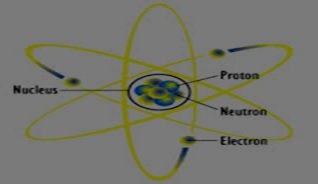
Clearly, Rutherford’s model was not sufficient to explain experimental observations. Some sort of modification was needed and this was provided by Neils Bohr.
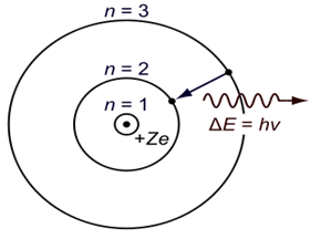
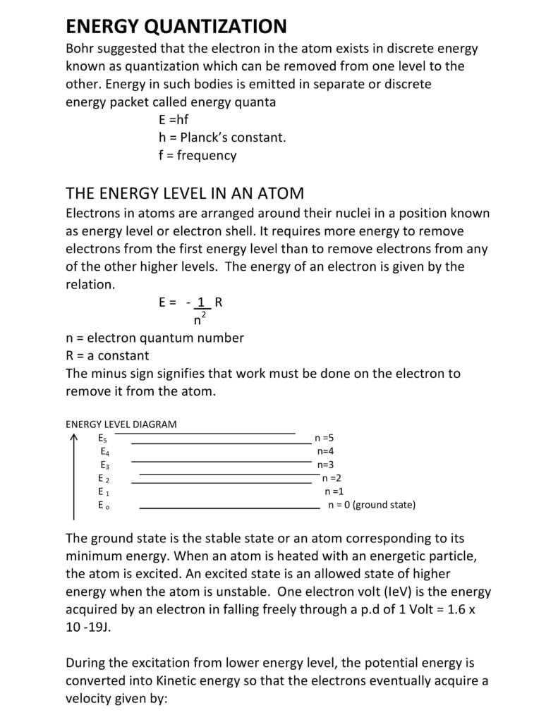
He suggested a model of a hydrogen atom in which
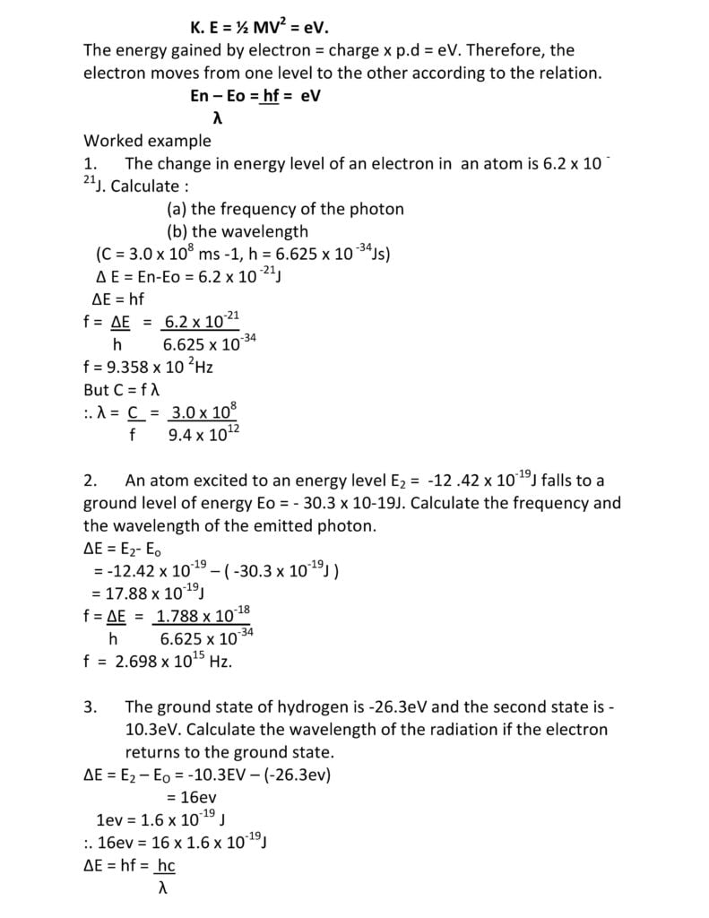
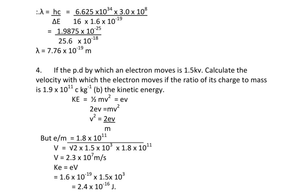
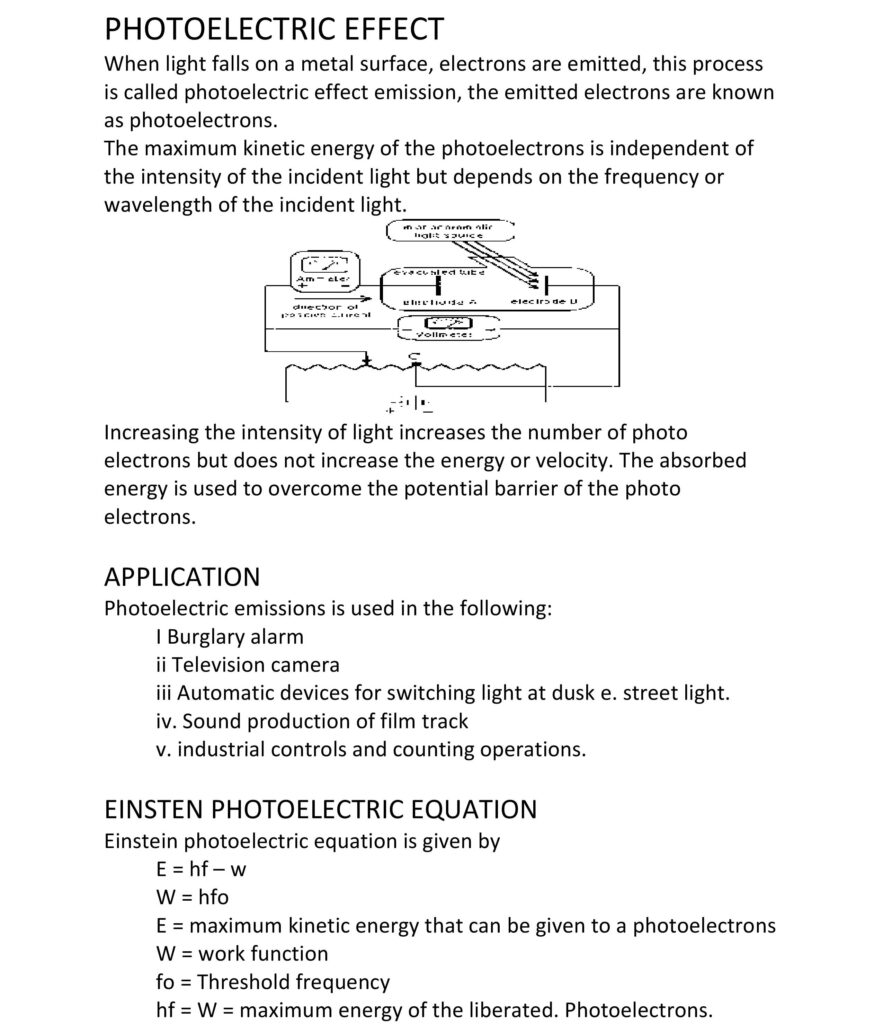
When such a jump occurs, a single photon of light would be emitted whose energy is given by
hf = Eu – El
Eu = Energy of upper state
El = energy of lower state
h = Planck constant (h = 6.67 x 10⁻³⁴ Js)
f = frequency of emitted light
Bohr was able to account for the appearance of a line spectrum rather than a continuous spectrum.
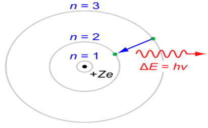
An electron absorbs energy when it transfers to a higher energy level (excitation) Photon An electron emits a photon when it moves to a lower energy level.
iii. The third postulate of Bohr’s model was that angular momentum values of the electron in an atom are quantized, that is, they are restricted to a limited number of discrete values that are integral 9n0 multiples of a constant, Planck’s constant (h) divided by 2 π. That angular momentum
L =n (h)
2π n = 1,2,3,4…
The integral n is called a quantum number
The Bohr model is also known as the Bohr–Rutherford model since it was an extension of the Rutherford planetary model. The great success of Bohr’s theory is that;
This model visualizes the atom as consisting of a tiny nucleus of radius of the order of 10-10 – 10-15m. The electron is visualized as being in rapid motion within a relatively large region around the nucleus, but spending most of its time in certain high-probability regions. Thus, the electron is not considered as a ball revolving around the nucleus but as a particle or wave with a specified energy having only a certain probability of being in a given region in the space outside the nucleus. The electron is visualized as spread out around the nucleus in a sort of electron – cloud.
Chemists prefer to consider the electron in terms of a cloud of negative charges (electron cloud), with a cloud being dense in regions of high electron probability and more diffuse in regions of low probability.
The probability of finding the electron inside the spherical boundary is high. The probability then decreases rapidly as the distance of the thin shell from the nucleus increases.
Today we consider the atom as made up of tiny but massive nucleus at the centre and outside the nucleus is a cloud of electrons which move in wave-like orbits or shells around the massive nucleus. The nucleus consists of protons which carry positive changes and neutrons which carry no charge. The neutron and proton together constitute the nucleon. All the mass of an atom is concentrated in the central nucleus. The protons, neutrons and electrons are the fundamental sub atomic particles of the atom.
The electron is the lightest particle of an atom, with a mass (Me) of 9.10-31kg and an electronic charge e- = 1.6 x 10⁻¹⁹ C.
The proton has a mass of 1.67 x 10⁻²⁷kg which is over 1836 times heavier than the mass of an electron. It carries a positive charge, e+ = 1.67 x 10⁻²⁹ c ( i.e e+ = e- = 1.6 x 10 -10). There are the same number of protons in the atoms of different elements.in a neutral atom, the number of protons equals the number of electrons.
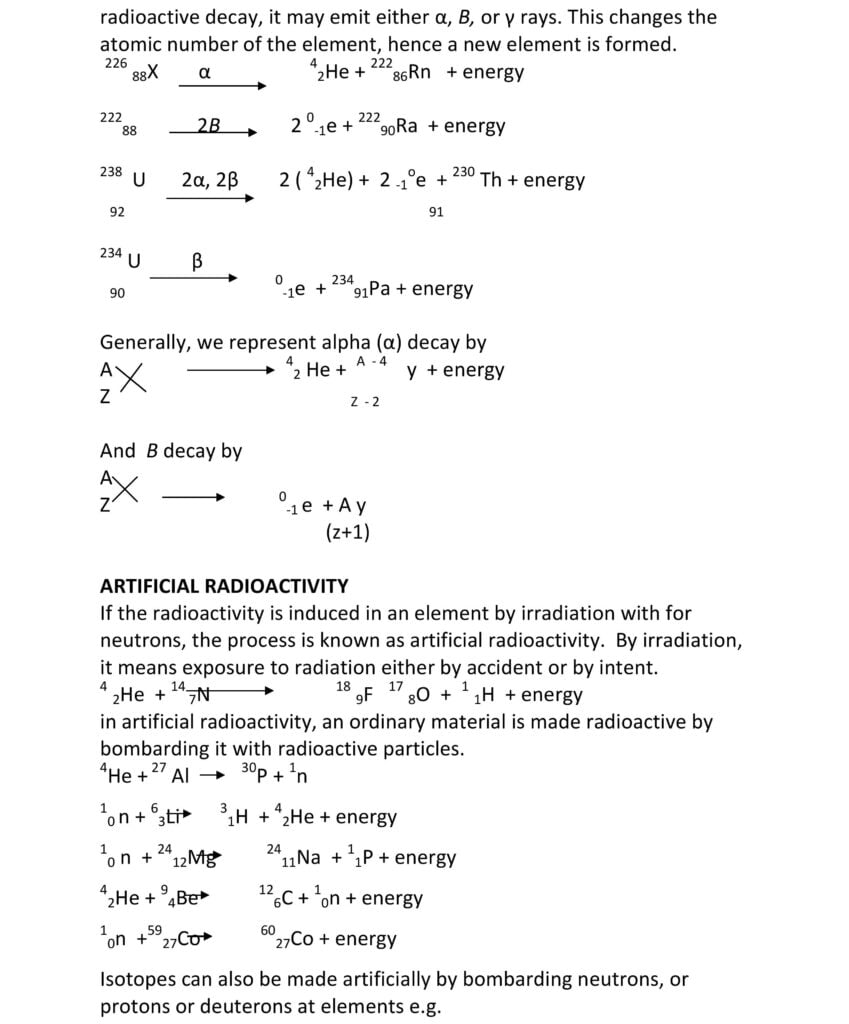
We denote the atom of an element X by AzX
A = mass number
Z = atomic number
The atomic number or proton number (Z) is the number of protons in the nucleus of an element. The mass number or nucleon number (A) is the total number of protons and neutrons in an atom of an element
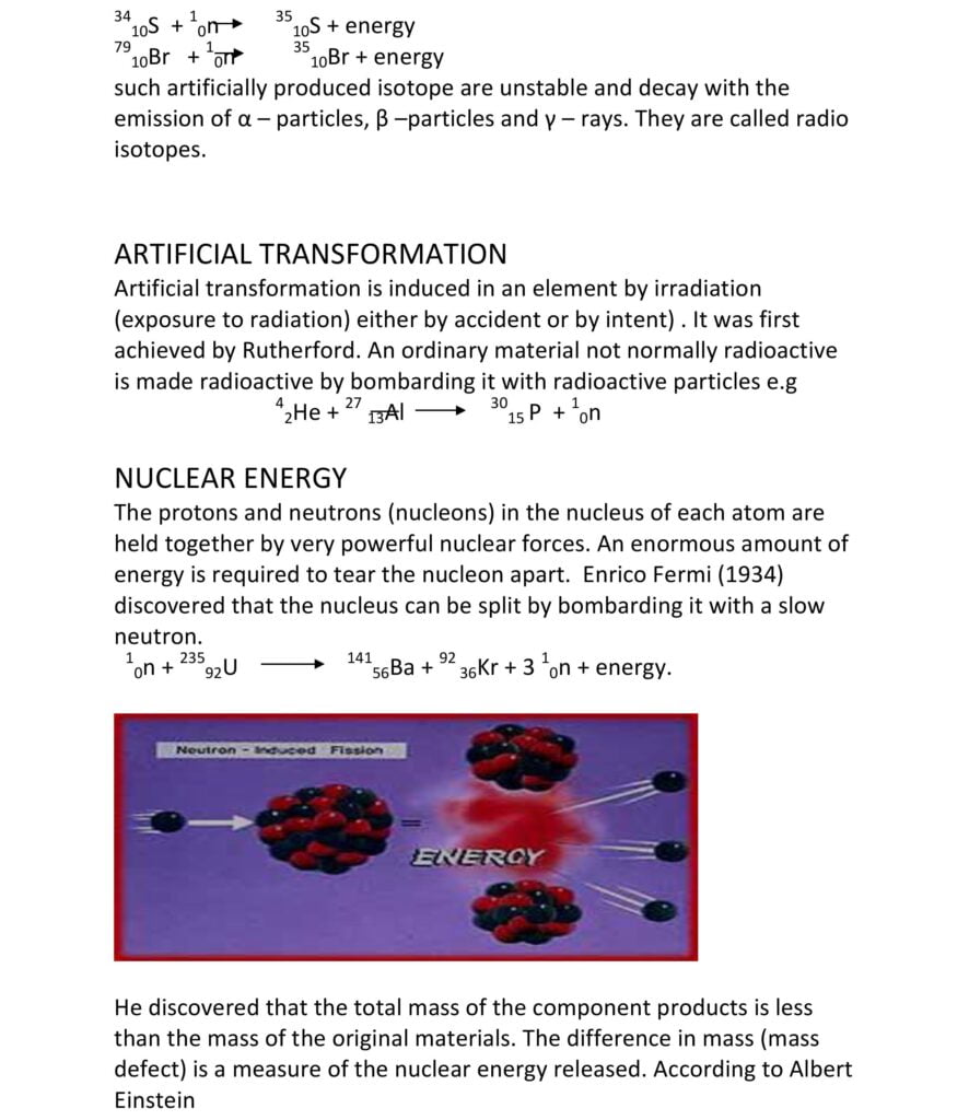
Isotopes are atoms of the same element which have the same atomic number (X) but different mass number. Isotopes are thus atoms with the same number of protons, but different number of neutrons. Isotopes have similar chemical properties because they have the same number of electrons around the nucleus. Chemical combinations is due to an exchange of outer or valence electrons between elements.
136Cl (6 protons, 6 electrons, 7 neutrons)
178O (8 protons, 8 electrons, 9 neutrons)
188O (8 protons, 8 electrons, 10 neutrons)
238\592U (92 protons,92 electrons, 143 neutrons)
23492U (92 protons, 92 electrons, 142 neutrons)


The word satellite refers to a body orbiting a larger one. There are natural satellites (e.g the Earth and other planets orbiting the Sun), and artificial satellites such as; Communication Satellites (that transmit telecommunication signals), Global Positioning Satellites (that allow for the identification of locations on the Earth) and Meteorological Satellites (that monitor weather and climate patterns). Examples of Nigeria satellite includes; Niger-SAT 1 (a disaster-monitoring microsatellite), NICOM-SAT 1 (for mobile phone and internet services. However due to the failure of its solar cells system, the satellite has ceased to function).
All satellites have some common basic components that work together to form the following systems;
Other components include; solar cells, batteries, command antenna, communication antenna, radio receivers and transmitters, rocket fuel, rocket motor, rocket thrusters, cameras.
Semiconductors are crystalline or amorphous solids with distinct electrical characteristics.
They are of higher of higher resistance than the typical conductors but of lower of lower resistance than the insulators. Their resistance decreases with temperature – a behavior opposite to that of metals. Their conducting properties can be altered in useful ways by the deliberate introduction (‘’doping’’) of impurities into the crystal structure.
Doping greatly increases the number of charge carriers (holes and electrons) within the crystal.
There are two major types of impurities; the donor and the acceptor. Antimony, Arsenic and Phosphorus are typical donor elements while Aluminum, Boron and Gallium are good acceptors. Addition of donor element produces the n–type semiconductor while the addition of acceptor element results in the p–type semiconductor.
The n-type semiconductor contains mostly free electrons, it has excess electrons (i.e its charge carriers are the excess electron), and a p-type semiconductor contains mostly free holes, it has a shortage of electron (i.e. its charge carriers are the excess holes).
A single semiconductor can have many p- and n- type regions when doped under precise conditions. The junction between these regions are referred to as the p-n junction. Doping lowers the resistance of a semiconductor but also permits the creation of semi-conduction junction. The behavior of charge carriers at this junction is responsible for its usefulness in diodes, transistors and all modern electronics. The most widely used semiconductors are Silicon, Germallium and compounds of Gallium. Elements located where the metalloids are on the periodic table are usually used as semiconductors
Electric current is simply electric charge in motion. In conductors such as cables or wire, the current consist of a swam of moving electron. Electric cells are chemical devices, which are capable of causing an electric current to flow.
This produces electric force, which pushes the current along. If there is a complete circuit of conductors by which current can leave from one end to terminal of the cell and travel round to the other terminal, a current will flow. This current will be the at any point round the circuit and of the line is broken, the current is stopped or switched off. The electrons flow from the negative terminal or cathode of the cell to the procedure terminal or anode
Electric cells are divided into two namely: the primary cells and the secondary cells
These are those cells in which current is produced as a result of an irreversible chemical charge.
These cells are those which can be recharged when they run down by passing current backwards through them. There are three components in a cell. Two of them are electrodes in the primary cell, the two electrodes are of different metals (graphics are often used) the third item is the container bearing the electrolyte. Examples of electrolytes are strips of aluminium, Carbons (graphite) copper, iron lead and zinc
A simple cell can be made by placing two different electrodes (metals) in an electrolyte. Two wires are then used to connect these metals to a voltmeter, an instrument that measures the potential difference between any two points in an electric circuit. If a deflection is noticed it means that the cell creates a voltage.
If the deflection is done to the right it means that the electrode, or anode, which is connected to the positive terminal of the voltmeter is the positive electrode, or anode, while the one is connected to the negative terminal is the negative electrode or cathode. If the deflection is however done to the left, a reconnection should be done. The two major deflects of a simple all are polarization and local action
The cell is characterized by the release of “hydrogen bubbles.” The bubbles collect at the positive electrode and insulate it. This shows down and eventually stops the working of the cell. This defect is called polarization. This defect can be corrected either by occasionally brushing the plates, which is highly inconvenient, or by using a depolarizer e.g. manganese oxide. This oxides hydrogen to form and so removes the hydrogen bubble.
This occurs when pure zinc is not in use. The impurities in the zinc results in the gradual wearing away of the zinc plates. This can be prevented by cleaning the zinc with H2SO4 and then rubbed with mercury. The mercury amalgamates the zinc by covering the impurities thereby preventing it from coming into contact with electrolyte.
Leclanche cells are of two types: the wet and the dried types. The wet leclanche cell consists of a zinc rod at the cathode in a solution of ammonium chloride contained in a glass vessel. The anode is a carbon rod contained in a porous pot and is surrounded by manganese chloride as a depolarised An e.m.f. Is set up by the zinc, the carbon and the electrolyte, which drives a current from zinc to carbon through the cell. This carbon is at a higher potential than the zinc.
When an external circuit is connected to the cell, current flows from carbon to zinc out side. The e.m.f is set up because zinc reacts with the ammonium chloride to form zinc chloride, ammonia and hydrogen, and electrons are released. These electrons flow from the zinc plate to the carbon plate outside the cell. Hydrogen reacts with the manganese dioxide and oxidizes it to form water.
The e.m.f of a leclanche cell is 1.5 v. Its defect includes When the cell has worked for some time, the rate of hydrogen production becomes greater than the rate at which it is oxidized by the manganese dioxide, hence the formation of polarization. Therefore, the cell must be allowed to rest from time.
These primary cells are restricted to intermittent current supply because they do not give continuous service. They are too heavy to carry about without spilling the liquid for the dry leclanche cell, the defect of heaviness is overcome. The ammonium chloride electrolyte is a jelly-like material and not aligned solution. The positive electrode is a carbon rod surrounded by a packed mixture of manganese dioxide and powered carbon, inside a zinc container, which is the negative electrode.
The dry can be carried about easily E.g. torch batteries and transistor radio batteries. Due to local action, they deteriorate after some time.
This is also a primary cell invented to counter the problem of polarization. The zinc rod is the negative electrode while the positive electrode is the container. The electrolyte is dilute tetrasulphate (vi) acid contained in a porous pot around the zinc rod, and the depolarize is copper tetraoxosulphate (vi) in the surrounding copper container. The diaphoreses is much more efficient than the leclanche cell.
Secondary cells are of two main types: lead-acid accumulator, and the alkaline or Nife accumulation. The lead-acid accumulator. This is the most common one. It consist of lead oxide as the positive electrode, lead as the negative electrode and tetra oxosulphate (vi) acid as the electrolyte. During the discharge, when the cell is given out current both plates gradually charge to lead tetraoxosulphate (vi) while the acid gradually becomes more dilute and the density decreases.
When fully charge the relative density and e.m.f. of the cell are 1.25 and 2.2v respectively. But when discharge they are reduced to 1.5 and less than 2.0v respectively. The rod density of the cell should not be allowed to drop 1.15 before it is recharged.
1 The liquid level must be maintained by using distilled H2 O
The name is gotten from the chemical symbol nickel (Ni) and iron (Fe). The positive electrode is made of nickel hydrogen while the negative plate is either of iron or calcium. The electrolyte is potassium hydroxide dissolve in water. This cell last longer and lead acid cells, keep their charge longer and they require less maintenance. They are used for emergencies in factories and hospitals. They are expensive and bulky with a small e.m.f value, about 1.25v.
This Is the process whereby a liquid conducts electricity by the movement of positive and negative ions within the liquid while undergoing chemical changes.
These are liquid, which allows the electricity through them is called electrolytes. Such electricity is salt solutions, alkalis and dilute acids (acidulated water).
These are liquids, which do not allow electricity to pass through them. Such liquids include distilled water, alcohol, liquid paraffin and sugar solution. NOTE-: metals and hydrogen are deposited at the cathode, while non-metals and oxygen are deposited on the anode. The anode may dissolve in solution. Electrolysis does not manufacture electric charges and it is the “splitting’ of compounds by electricity. e.g. water decomposes into oxygen and hydrogen by electric current. Electrolysis begins when the electric circuit is completed and ends abruptly when the electric circuit is broken FARADAY’S
Faraday’s first law states that the mass of a substance liberated during the process of electrolysis is proportional to the quantity of electricity passed through the electrolyte Faraday’s second law of electrolysis states that the relative masses of substances liberated by the same quantity of electricity are proportional t their chemical equivalents.
If M is the mass of substance deposited when a current q flows for time t, then the quantity of electricity of electricity which flows is flows is It, and m = Z It. Where, Z = electrochemical equivalent (e.c.e) the substance. …. Z = m = It I = current in A t = time in see m = mass of substance in grammes.
In industry, electrolysis is used in the electroplating of metals, purification of metals and electrolytic production of metals from compounds.
(1) Electroplating
This process is used in coating cutlery and other articles with copper, silver, chromium, nickel or gold. The article to be plated is used as the cathode and the coating metal is used as the anode. The electrolyte is a solution of a salt of a salt of the plating metal. For example, in the silver –plating of a spoon is made the cathode, pure silver is the anode, and silver nitrate solution is the electrolyte (see figure below).
Two anodes would be placed, one on each side of the spoon so that back and front would be plated at once. The silver nitrate dissociates in solution into silver ion and nitrate ions. AgNoAg+ + No3 When electricity is passed through the solution, the Ag ions move towards the cathode where they are discharged and the spoon becomes coated with metallic silver. The NO remains in solution, combining with silver from the anodes to form more silver nitrate, thus staying at its original concentration.
In the electrolysis of copper sulphate using copper electrodes, copper is deposited at the cathode while at the same time the copper from the anode goes into solution. In purification of copper metal, the impure copper is made the anode while the pure copper is made the cathode. When current is passed, copper ions are dissolved from the anode and deposited at the cathode leaving the impurities behind. The pure copper is used in manufacture of electric cables because of its low resistance.
Metals such as aluminium, sodium and potassium are prepared from their molten chlorides or hydroxide by the process of electrolysis.
Application – D.C Motors, moving coil galvanometer.
This is a field representing the joint interaction of electric and magnetic forces. It is exerted on a charged particles. The force on a charge q moving with a velocity v (less than the velocity of light is given by F = q ( E + v x B ) A conductor carrying an electric current when placed in a magnetic field experiences a mechanical force. It can be demonstrated by using two metal rails fixed on each side of a powerful horse-shoe magnet. A copper rod is placed across the rails.
When we pass current through this copper rod, it is observed that the copper rood rolls along the rails, towards the right. If by adjusting the rheostat, we cause more current to flow through the rod, we will observe that the rod moves faster. Thus, the force on the rod increases when the current increase.
The direction of the force on a current carrying conductor placed perpendicular to the magnetic field is given by Fleming’s left-hand rule which is stated as follows: If the thumb, forefinger and middle finger are held mutually at right angles to one another with the fore-finger pointing in the direction of magnetic-filed, and the second finger in the direction of Current, then the thumb will point in the direction of Motion for force producing motion.
(a) a rectangular coil of insulated wire, known as armature,
(b)a powerful magnetic field in which the armature turns is provided by two curve pole pieces of a powerful magnet.
(c) a commutator consisting of a split copper ring, two halves of which are insulated from each other. (d) two carbon brushes which are made to press lightly against either side of the split-ring commutator
It consists essentially of:
A transformer is an electrical device for changing the size of an a.c. voltage. It acts to increase or decrease the em.f of an alternating current. It consists of two separate sets of coil, the primary coil and the secondary coil. The primary coil is the input winding of turns of wire and the secondary coil is the output winding. The coils are wound round a soft-iron core. The soft-iron core acts to increase and concentrate the magnetic flux within the core. It is also laminated, i.e. it consists of sheets of soft-iron insulated from each other instead of a solid block of iron. This lamination reduces loss of energy in the form of heat due to eddy currents introduced in the core.
Mutual inductance is the flow of induced current or voltage in a coil due to an aternting or varying current in a neighbouring coil.
The total flux linking the two coils is proportional to their number of turns. The induced e.m.f in the secondary coil (Ep) depends on the e.m.f. in the primary coil and on the ratio of the number of turns in each
:. ES = Ns EpNp
In an ideal transformer with a 100% efficiency, the power developed in the secondary coil is equal to the power developed in the primary coil.
:. Es= Ip
Ep Is
Hence, Es = Ns = Ip EpNp Is.
To use a transformer to increase an applied voltage, i.e to make Es greater than Ep, Ns must be grater than Np . such a transformer which increases or steps up the applied or primary voltage is called a step-up transformer. In a step-up, the primary current is greater than the secondary current but the primary voltage is less than the secondary voltage.
There are energy losses in practical transformers due to:
turns ration = Ns = 120 = 2
Np 60
It is a step-down transformer because secondary voltage is less than primary voltage (132 < 220)
ii the cost of using it for 24hrs at 30k per kwh.
Primary or input power = IpVp
= 0.7 x 220 = 154w
secondary (output power ) =IsVs = (Is x 15 )w p = iv
p = V
Is = 40
Total current taken by the 3 lamps in parallel = 3 x 2.67 =8A
:. Output power = 8 x 15 = 120 W Efficiency = Output Power X 100
Input Power
= 120 x 100
Power consumed = 0.7 x 220 Kw
1000
Total power consumed in 24 hrs
= 0.7 x 220 x 24kwh
1000.
Cost at 30k per kwh
= ( 0.7 x 220 X 24 X 30
100
= N1
Power generated at power stations is distributed over large distances to consumers through metal cables, Power can be transmitted either at low current and high voltage or at high current and low
voltage. Because the metal cables through \h which the power is transmitted have a certain amount of electrical resistance, transmitting power at high current will lead to loss of energy in the form of heat. To avoid this, this power is transmitted at high voltage and low current. This is known as high-tension transmission.
Low currents lead to low energy loss. It also requires thinner cables, cost of cable materials is considerably reduced if power is transmitted with low current and high voltages.
Step-down transformers are used to reduce the high transmitted voltages to lower voltages required in home and factories.
A machine is a device that aids man in the performance of work and makes the work easier, quicker and more convenient. Machines use energy to multiply a force, change the direction of a force, transform or transfer energy or multiply speed.
Machines play a pivotal role in modern society by enhancing human capabilities, streamlining processes, and enabling the accomplishment of tasks that would be challenging or impossible to achieve through manual effort alone. These versatile devices utilize various principles of physics and engineering to manipulate forces, energy, and motion in ways that significantly benefit human endeavors.
Machines serve as indispensable tools that empower humans to achieve feats beyond their natural capabilities. Whether by amplifying force, altering direction, transforming energy, or streamlining tasks, machines have revolutionized the way we live, work, and explore the world around us.
Machines are needed to make our work easier, quicker and more convenient. Machines are employed to save work and multiply our ability to do work. They increase the force we need, add some energy, do work we could not do before.
Machines especially those with moving parts should be checked routinely for regular maintenance and probably repairs. This should be done to ensure the normal operation of machines and to prevent any possible breakdown. Maintenance requires things like lubrication, cleaning and replacing minor parts to ensure smooth running of the machine.
Machines are repaired so that we can put it into continuous use. The defective parts of the machine are replaced with new ones. Repair of machines is cost-effective instead of purchasing and installing new ones
Regular maintenance increases the efficiency and speed of machines. It conserves the energy and life of machines and prevents the replacing of the parts of the equipment before the scheduled time. Regular maintenance of machines ensures the safety of the operator since if the machine is not in good condition, it might lead to a major accident. Regular maintenance of machines also saves money and time.
A dam is a barrier constructed across a stream or river to impound water and raise its level for various purposes such as generating electricity, irrigation and water supply systems, increase river depths for navigational purposes, to control water flow during times of flood and drought, create artificial lakes for fisheries and recreational use. In Nigeria, dams are used mainly for water supply systems, energy production (hydroelectricity) and for irrigation purposes. The following are some of the dams in Nigeria:
The power of falling water is unlocked by a hydroelectric dam in the form of electricity. Hydroelectric power produced by hydroelectric dams accounts for 20% of the world’s total production of electrical energy.
A large quantity of water is stored in a reservoir or dam. The height or depth of the stored water determines how much electricity can be generated. As the depth increases, the generation of electricity also increases. A control gate is used for releasing/blocking water from the dam. Depending upon the electricity requirements, the gate is opened.
The released water from the dam reaches the turbine blade through the penstock. The proper slope and diameter of the penstock is important for the efficiency of the dam.
The turbine consists of a number of large fan blades and a spindle. The spindle rotates when the water strikes the blades. Thus, the power of flowing water is converted to the rotational power of the spindle. The spindle of the turbine is connected to the alternator where rotational power of spindle is converted into electrical power. The produced electricity is the distributed to the grid. The outflow of water from the turbine is released to a river.
A rocket or rocket vehicle is a missile, spacecraft, aircraft or other vehicle which obtains thrust from a rocket engine.
A satellite is an object that goes around or orbits a larger object such as a planet. While there are natural satellites like the moon, hundreds of man-made satellites also orbit the earth.
In all rockets, the exhaust is formed entirely from propellants carried within the rockets before use. Rocket engine works forward simply by throwing their exhaust backwards extremely fast. Rocket engine employs the principle of jet propulsion.
Rocket vehicles are often constructed in the archetypal tall thin rucked shape that takes off vertically but there are usually many different types of rockets including:
Rockets work by accelerating gas to very high speeds inside and then letting the gas escape from the back of the rocket.
Satellites are celestial bodies orbiting round a planet or star. Artificial satellites are used for many different things including scientific studies of the solar system, worldwide telecommunications, military intelligence, television and earth monitoring for weather or climate studies.
Rockets consist of a propellant, a place to put propellant (such as a propellant tank) and a nozzle. They may also have one or more rocket engines, directional stabilization devices such as fins, vernier engines or engines gimbals for thrust vectoring, gyroscopes and a structure (typically monologue) to hold these components together. Rockets intended for high speed atmospheric use also have an aerodynamic fairing such as nose cone which usually holds the payload.
As well as these components, rockets can have any number of other components such as beings (rocket planes), parachutes, wheels (rocket cars) etc. Vehicles frequently possess navigation systems and guidance systems which typically use satellite navigation and inertial navigation systems.
The main components of satellite (human-made satellite) are communication capabilities with earth, a power source and a control system to accomplish its mission.
Nigeria made its debut in satellite space technology on September 27, 2003 when it launched Sat-1 aboard a Russian rocket. The Niger-sat1 carries an imaging payload that provides satellite images of 32m resolution with a swath width of 600km using push broom scanning in three spectral bands (Red, Green and Near infra-red) and 3-5 days revisit and a daily revisit when in constellation with four other satellites.
These are the patch antennas, QFH antennas, camera banks, module stack which consists of SSD4, OBC386, GPS/SA1100, OBC186, ADCS power, yam wheel, propulsion tank and propulsion controller
It is in space and is being operated from the ground station (mission control ground station) in Abuja, Nigeria for telemetry, tele-control and command of the spacecraft.
It is used for monitoring of boundaries and oil pipelines, ground water investigation, oil theft and smuggling activities band environmental observations. It is used for better planning and effective disaster management.
It is Nigerian communications satellite. It is also called NIGCOM-SAT 1. It was launched in May, 2007 by along March 3-B rocket in China.
It is a superb hybrid geostationary satellite with a launch mass of 5150kg, a service life of at least 15 years and a reliability of more than 0.70 at the end of its lifetime. Located 42.5E, with forty transponders (30 active andb10 redundant)
Nigcomsat Limited Incorporated operates and manages Nicom-Sat 1. Nicom-Sat 1 is useful in broadcasting, telecommunications, internet and multimedia services for Africa.
.
.
.